None destructive testing NDT
The process of inspecting testing and evaluating components for differences in characteristics without destroying the serviceability of the part or system. NDT techniques are used to detect service related conditions caused by wear, fatigue, corrosion, stress or other factors that affect reliability.
Ultrasonic Testing (UT)
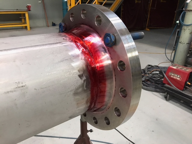
In ultrasonic testing, high frequency sound waves are introduced into a material via an ultrasonic transducer connected to a UT gauge coupled to the test object by couplant, to detect imperfections. There are two methods of receiving the ultrasound waveform, reflection and attenuation.
The most widely used technique reflection (or pulse-echo) mode, whereby sound is introduced into a test specimen and reflections (the echoes) coming from the internal imperfection or the part’s geometrical surfaces such as the back wall of the object are returned to the device.
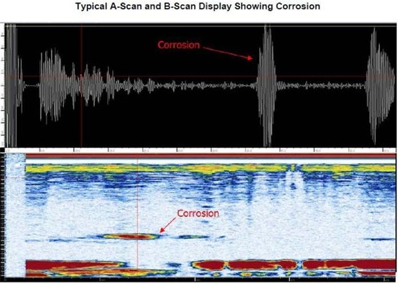
The diagnostic device displays the results in the form of a signal with an amplitude representing the intensity of the reflection and the distance, representing the arrival time of the reflection.
In attenuation (or through-transmission) mode, a transmitter sends ultrasound through one surface, and a separate receiver detects the amount that reaches the other surface after traveling through the object. Imperfections or other conditions in the space between the transmitter and receiver reduce the amount of sound transmitted, and in so doing, revealing their presence. Using the couplant increases the efficiency of the process by reducing the losses in the ultrasonic wave energy due to separation between the surfaces.
Advantages of Ultrasonic Testing
- High penetrating power, which allows the detection of flaws deep in the part.
- High sensitivity, permitting the detection of extremely small flaws.
- Only one surface need be accessible.
- Greater accuracy than other non-destructive methods in determining the depth of internal flaws and the thickness of parts with parallel surfaces.
- Some capability of estimating the size, orientation, shape and nature of defects.
- Nonhazardous to operations or to nearby personnel and has no effect on equipment and materials in the vicinity.
Magnetic Particle Testing (MPT or MPI)
Or Magnetic particle inspection (MPI) is a non-destructive testing (NDT) process for detecting surface and partially subsurface discontinuities in ferromagnetic material such as iron, nickel, cobalt, and some of their alloys. The process puts a magnetic field into the part.
The presence of a surface or subsurface discontinuity in the material allows the magnetic flux to leak. Dry or wet ferrous iron particles are applied to the part.
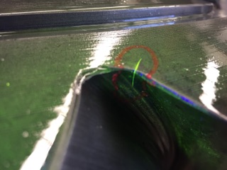
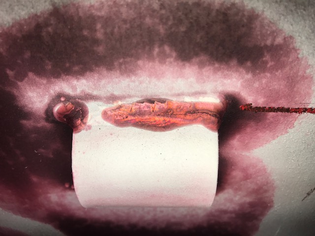
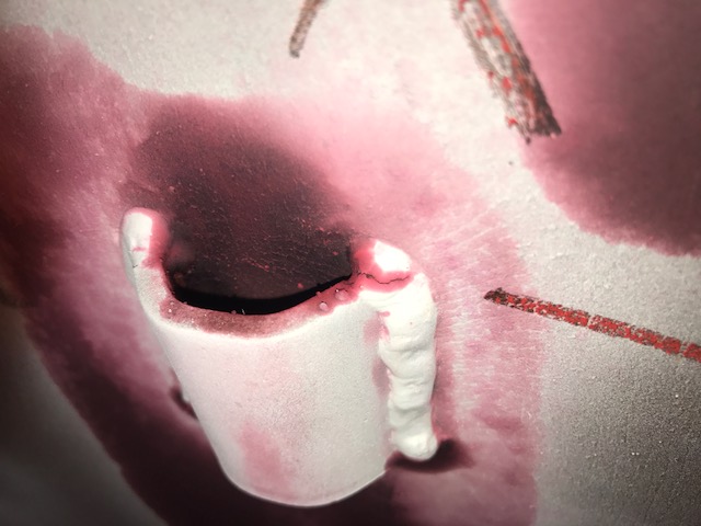
If an area of flux leakage is present, the particles will be attracted to this area. The particles will build up at the area of leakage and form what is known as an indication. From the Visible indication, the location, size and shape can be assessed.
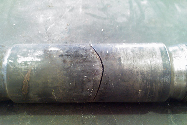
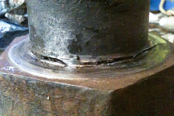
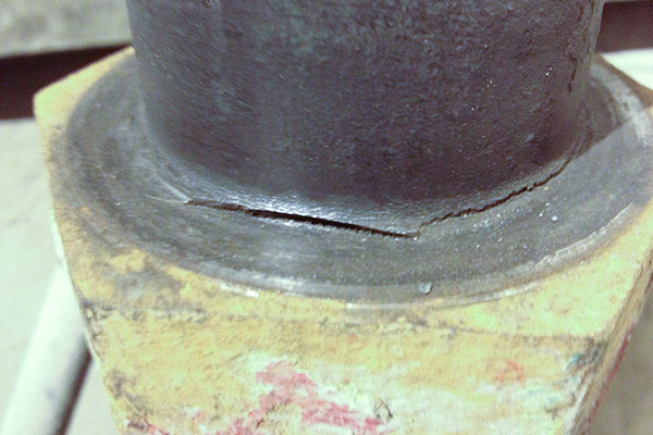
Penetrant Testing (PT)
Penetrant testing (PT) or Dye penetrant inspection (DPI), which is also called liquid penetrant inspection (LPI) are a widely used low-cost inspection method they are used to locate defects which break the surface of non-porous materials such as metals, plastics, or ceramics.
The penetrant may be applied to all non-ferrous materials and ferrous materials, although for ferrous components magnetic-particle inspection MPI is often preferred for its subsurface detection capability’s.
LPI is used for castings, forgings and welding to detect surface defects such as hairline cracks, surface porosity, leaks in new products, and fatigue cracks on in-service components.
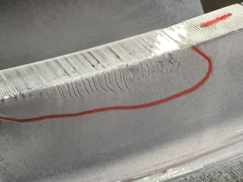
DPI is based upon capillary action where low surface tension fluid penetrates into clean and dry surface-breaking discontinuities. Penetrant may be applied to the test component by dipping, spraying, or brushing. After adequate penetration time has been allowed, the excess penetrant is removed, and a developer is applied.
The developer helps to draw penetrant out of the flaw where a invisible indication becomes visible to the inspector. Inspection is performed under ultraviolet or white light, depending upon the type of dye used—Florescent or no fluorescent (visible).
EMATS
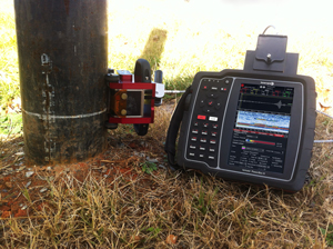
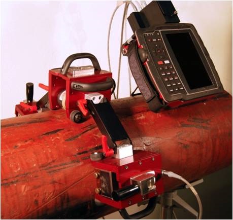
Electro-Magnetic Acoustic Transducer (EMAT) is an Ultrasonic Testing (UT) technique that generates sound in the component being inspected rather than the transducer. Because the sound is generated in the part inspected instead of the transducer, EMAT is a completely non-contact technique. This gives it significant advantages over more conventional piezoelectric transducers.
- Non-contact EMAT technique.
- Permits 100% inspection of boilers instead of spot checking at up to 15cm/s of scanning speed.
- Ultrasonic EMAT technique provides accurate thickness readings with minimum surface preparation.
- Only system capable of measuring remaining wall thickness on heavily corroded tubes.
- Capable of detecting hydrogen damage, pitting and caustic gouging.
- Works on carbon steel and clad materials.
- Sensor with integrated encoder and light indicators for fast visual alert to the operator.
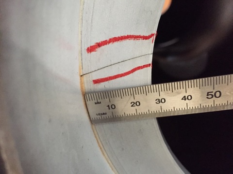
Boltprep has pioneered the use of EMAT’s for large gear and pinion teeth inspections.
Until recently the two main methods of inspecting gear and pinion teeth were a combination of Eddy current (EC) or Magnetic particle inspection (MPI). Both of which are not ideal as MPI suffers from an inability to position the yoke to best inspect the root of the teeth and Eddy current can only inspect the surface and subsurface to a few thousands of an inch
The EMAT’s gear and pinion teeth inspection system uses Surface / Rayleigh waves to detect surface and subsurface discontinuities. EMAT’s surface waves are confined to within a wavelength of the surface along the direction of propagation. Surface waves combine both a longitudinal and transverse motion to create an elliptic orbit motion.
EMAT’s Surface waves are very sensitive to surface defects and are useful as they follow the curves of the surface they are confined too, this means that they can be used to inspect hard to reach locations such as the root of the gear teeth.
- Dry and non-contact.
- Temperatures from -50ºC up to 200ºC, with standard probes.
- Temperatures as low as -100 ºC to as high as +750 ºC can be inspected with specially designed transducers.
- Fast scanning, permits line and C scans of complete surface.
- Coated surfaces 1-3mm thick (depending on frequency).
- Not affected by surface conditions (wet, oily, rough, oxidized).
- Guided waves can cover large areas.
- Provide access to hidden areas and detect defects with attenuation or reflection techniques.
- Capable of detecting very small defects (0.3mm cracks) in different orientations.
- Ability to normalize the signal for self-calibration.
Boiler inspection
- Exclusive boiler mapping software application permits easy visualization of boiler walls with results of inspection for fast analysis and interpretation.
- Proven technique with hundreds of boilers and thousands of kilometres of inspected tube worldwide and is designed for detecting and measuring wall loss, hydrogen damage and caustic gauging in boiler tubes.